Heat exchanger theory leads to the heat exchanger design equation that relates the overall heat transfer coefficient, heat transfer surface area, and log mean temperature difference to the rate of heat transfer. This heat exchanger design equation is used to find the area needed for heat exchangers.
Introduction
The heat exchanger design equation can be used to calculate the required heat transfer surface area for a variety of specified fluids, inlet and outlet temperatures and types and configurations of heat exchangers, including counter flow or parallel flow. A value is needed for the overall heat transfer coefficient for the given heat exchanger, fluids, and temperatures. Heat exchanger calculations could be made for the required heat transfer area, or the rate of heat transfer for a heat exchanger of given area.
The Heat Exchanger Design Equation
Heat exchanger theory leads to the basic heat exchanger design equation:
Q = U A ΔTlm, where
Q is the rate of heat transfer between the two fluids in the heat exchanger in But/hr,
U is the overall heat transfer coefficient in Btu/hr-ft2-oF,
A is the heat transfer surface area in ft2,
and ΔTlm is the log mean temperature difference in oF, calculated from the inlet and outlet temperatures of both fluids.
For design of heat exchangers, the basic heat exchanger design equation can be used to calculate the required heat exchanger area for known or estimated values of the other three parameters, Q, U, and ΔTlm. Each of those parameters will now be discussed briefly.
Log Mean Temperature Difference
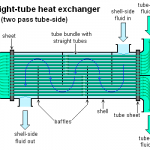
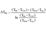 The driving force for any heat transfer process is a temperature difference. For heat exchangers, there are two fluids involved, with the temperatures of both changing as they pass through the heat exchanger, so some type of average temperature difference is needed. Many heat transfer textbooks have a derivation showing that the log mean temperature difference is the right average temperature to use for heat exchanger calculations. That log mean temperature is defined in terms of the temperature differences as shown in the equation at the right. THin and THout are the inlet and outlet temperatures of the hot fluid and TCin and TCout are the inlet and outlet temperatures of the cold fluid. Those four temperatures are shown in the diagram at the left for a straight tube, two pass shell and tube heat exchanger with the cold fluid as the shell side fluid and the hot fluid as the tube side fluid.

Recent Comments